


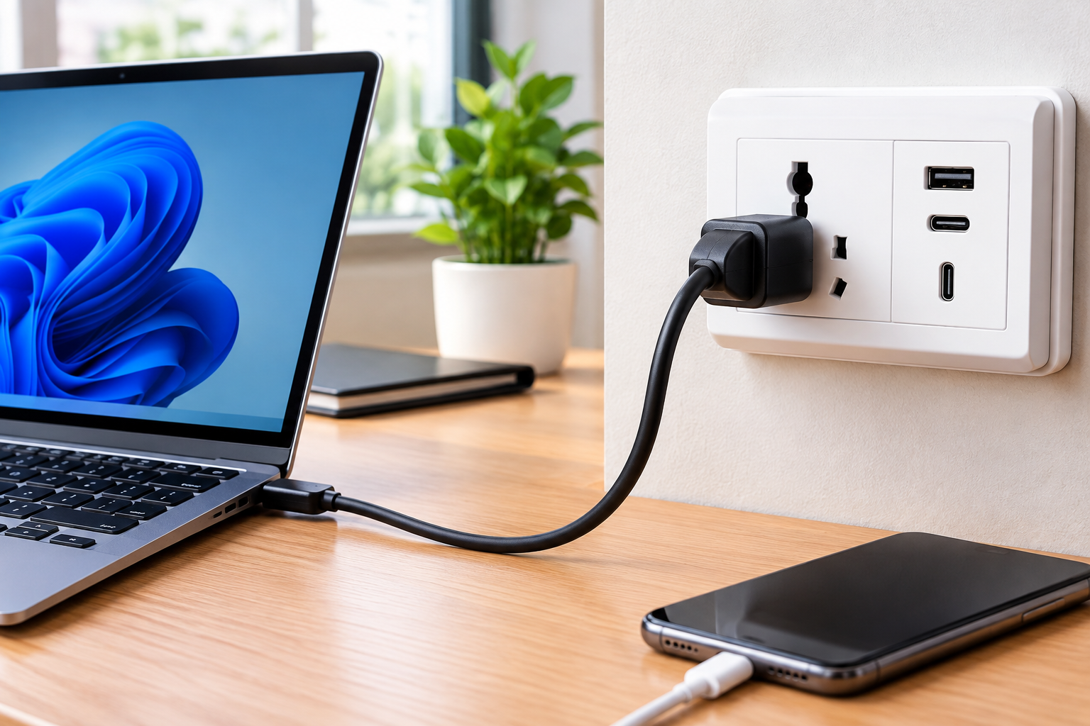
In modern computing, performance depends heavily on seamless communication between individual components. Whether you are assembling a custom gaming rig, upgrading an enterprise server, or simply trying to understand how hardware components interact, hardware interfaces play a fundamental role. Understanding how components connect, communicate, and power up ensures system stability, optimal speed, and longevity.
1. Understanding Central Processing Unit (CPU) Sockets
At the core of every system lies the central processing unit, and connecting it to the system requires a specialized physical and electrical interface: the CPU socket. This pin-array interface allows the processor to communicate directly with the motherboard without requiring permanent soldering.
Types of Socket Architecture
Hardware manufacturers use distinct structural designs to secure processors and deliver power cleanly:
- LGA (Land Grid Array): In an LGA configuration, the fragile connector pins reside on the motherboard socket itself, while the underside of the processor features flat gold pads. This design reduces the risk of damaging the expensive processor during installation. Most modern desktop architectures rely on LGA.
- PGA (Pin Grid Array): PGA places the connector pins directly on the underside of the processor chip, which then align with corresponding holes in the motherboard socket. While traditionally popular, PGA requires careful handling to prevent bent pins on the CPU.
- BGA (Ball Grid Array): Unlike LGA and PGA, BGA processors are permanently soldered to the motherboard using tiny solder balls. This approach is standard in ultrabooks, laptops, and compact embedded hardware where upgradability is traded for ultra-slim design profiles.
Structural Comparison Matrix
| Socket Type | Pin Location | Upgradability | Typical Use Case | Handling Risk |
| LGA | Motherboard | High (User-swappable) | Modern Desktops & Servers | Motherboard pins fragile |
| PGA | Processor | High (User-swappable) | Legacy Desktops & Laptops | Processor pins fragile |
| BGA | Direct Solder | None (Permanent) | Thin Laptops, Mobile Devices | Thermal stress during repair |
2. Common Desktop and Server Socket Generations
Matching the right processor family to its specific physical interface is crucial when planning system upgrades or custom builds.
High-Performance Desktop Interfaces
- LGA 1700: Designed to support hybrid core architectures with DDR4 and DDR5 memory compatibility, featuring an elongated rectangular physical footprint.
- LGA 1851: Built to accommodate newer generation desktop architectures with enhanced power delivery and expanded PCIe bandwidth.
- AM4: A long-lasting PGA platform that supported multiple generations of desktop processors, establishing a benchmark for platform longevity.
- AM5: A modern LGA platform featuring high-density LGA 1718 contacts, native PCIe 5.0 lanes, and dedicated DDR5 support.
Enterprise and Workstation Interfaces
Server and high-end desktop platforms require significantly larger pin counts to support quad-channel or octa-channel memory along with vast arrays of PCIe expansion lanes:
- LGA 4094 (Socket SP3): Engineered for high-core-count enterprise server processors, delivering high memory throughput and vast expansion capacity.
- LGA 4677: Built for multi-socket enterprise servers demanding extreme memory bandwidth and advanced data center workload processing.
3. Peripheral Connectivity: Expansion Slots and Data Interfaces
Beyond processor mounting, internal system performance relies on peripheral communication channels that connect graphics cards, ultra-fast storage drives, and add-in network cards.
+-----------------------------------------------------------------------+
|                            MOTHERBOARD                                |
|                                                                       |
|  +-------------------+        +------------------------------------+  |
|  |    CPU SOCKET     |=======>|       PCIe 5.0 x16 SLOT            |  |
|  |   (LGA / AM5)     | Direct |     (Graphics Processing Unit)     |  |
|  +-------------------+ Bus    +------------------------------------+  |
|            ||                                                         |
|            || High-Speed Lanes                                        |
|            \/                                                         |
|  +-----------------------------------------------------------------+  |
|  |                        M.2 NVMe SOCKET                          |  |
|  |                   (Ultra-Fast SSD Storage)                      |  |
|  +-----------------------------------------------------------------+  |
+-----------------------------------------------------------------------+
PCI Express (PCIe) Architecture
Peripheral Component Interconnect Express forms the high-speed bus backbone of modern custom rigs. PCIe slots come in physical sizes defined by line count:
- x1: Used for low-bandwidth devices such as sound cards, Wi-Fi adapters, and legacy expansion cards.
- x4: Commonly utilized for specialized capture cards, RAID controllers, and dedicated high-speed network interfaces.
- x16: The primary slot for high-performance graphics cards, offering maximum throughput directly to the processor lanes.
Storage Connections: M.2, SATA, and NVMe
- M.2 Interface: A versatile small-form-factor connection capable of routing both SATA interface signals and fast PCIe NVMe lanes directly across the motherboard surface.
- SATA Connectors: Traditional ribbon-cable connections suitable for standard 2.5-inch solid-state drives and high-capacity mechanical hard drives.
4. Power Delivery Networks and Pin Configurations
Stable power conversion is just as vital as data processing. High-performance components demand precise voltage levels delivered through multi-pin motherboard headers and modular power cables.
Motherboard and Processor Power Standards
- 24-Pin ATX Power Connector: Supplies baseline 3.3V, 5V, and 12V direct-current rails to motherboard chipsets, memory, and primary onboard logic.
- 8-Pin (4+4) EPS12V Connector: Delivers dedicated 12V power directly to the voltage regulator modules (VRMs) surrounding the main processor socket.
- 12V-2×6 / 12VHPWR Connectors: Modern high-density power interfaces designed to deliver up to 600 Watts of continuous power to modern high-draw graphics processing units over a single cable harness.
Internal Power Interface Overview
| Power Connector | Pin Count | Primary Output Voltage | Main Target Component |
| Main ATX | 24 Pins | 3.3V / 5V / 12V | Motherboard Chipset & Logic |
| EPS12V | 8 Pins (4+4) | 12V | Processor VRMs |
| PCIe Power | 6+2 Pins | 12V | Standard Expansion Cards / GPUs |
| 12V-2×6 | 16 Pins (12+4) | 12V | Next-Gen High-Draw GPUs |
| SATA Power | 15 Pins | 3.3V / 5V / 12V | Storage Drives & Hub Accessories |
5. Network Sockets: Physical Ports and Protocol Layering
Connectivity extends beyond the computer chassis to external networks through physical hardware ports and underlying software protocols.
Ethernet RJ-45 Physical Interface
The RJ-45 port remains the industry standard for wired network communication, offering shielding against electromagnetic interference and support for varying speed standards:
- 1 Gigabit Ethernet (1GbE): Standard for everyday web browsing and office networking.
- 2.5 Gigabit Ethernet (2.5GbE): Popular choice on modern enthusiast motherboards for high-speed local network storage transfers and smooth gaming.
- 10 Gigabit Ethernet (10GbE): Enterprise-grade networking required for large data centers, storage attached networks (NAS), and heavy media production environments.
Software Sockets in Network Architecture
In software engineering, a socket acts as an endpoint for receiving and transmitting data across a network. It pairs an IP address with a specific port number to establish communication streams between client systems and host servers.
+-------------------+                      +-------------------+
|   CLIENT SYSTEM   |                      |    HOST SERVER    |
|                   |                      |                   |
|  IP: 192.168.1.50 |   Network Data Stream |  IP: 192.168.1.100|
|  Port: 52114      |<====================>|  Port: 80 (HTTP)  |
|                   |   TCP/IP Communication|                   |
+-------------------+                      +-------------------+
Key Socket Types in Software Systems:
- Stream Sockets (TCP): Connection-oriented communication ensuring reliable, error-checked data transmission. Ideal for web browsing, secure shell sessions, and email transmission.
- Datagram Sockets (UDP): Connectionless communication focused on low-latency delivery. Essential for real-time video streaming, online multiplayer gaming, and live voice communication.
6. Best Practices for Hardware Installation and Troubleshooting
Working with delicate pin arrays and multi-pin electrical connections requires deliberate handling and physical safety procedures.
Safe CPU Installation Steps
- Inspect for Physical Defects: Check the motherboard pin array or processor underside under a bright light for misaligned or bent contacts.
- Align Orientation Markers: Locate the gold triangle etched onto the corner of the processor and align it precisely with the matching triangle symbol on the socket frame.
- Zero-Force Drop: Lower the processor straight down into position without applying downward force. The chip must sit entirely flat inside the mounting frame.
- Engage Retention Mechanism: Lower the tension arm and lock it beneath the retaining hook. Pressure will distribute evenly across the contact surface.
Resolving Connection and Power Failures
- System Fails to Post (Power-On Self-Test): Re-seat memory modules and verify that both the 24-pin main header and 8-pin processor power plugs are firmly clipped into place.
- Intermittent PCIe Dropouts: Inspect the retention clip on the graphics card slot. Clean edge connector contacts with isopropyl alcohol to remove oil or dust build-up.
- Thermal Throttling Under Load: Ensure proper thermal compound application between the processor top shield and cooling plate to eliminate microscopic air pockets.
7. Future Trends in Hardware Connection Standards
As component power demands rise and bus speeds push into higher frequencies, interface designs continue to evolve to eliminate signal degradation.
- Land Grid Array Density Increases: Modern platforms are moving toward higher pin counts within similar physical footprints to deliver extra power channels and faster memory routing.
- Direct Optical Connections: Future hardware buses may replace traditional copper trace signal paths with integrated optical interconnects, dramatically reducing latency while eliminating thermal buildup along signal paths.
- Universal Modular Power Layouts: Newer motherboard standards are shifting high-voltage delivery systems toward centralized rail layouts, decluttering internal cases and improving airflow management across custom systems.
By understanding physical pin layouts, electrical delivery requirements, and data interface protocols, technology enthusiasts and system builders can build, upgrade, and troubleshoot hardware systems with complete confidence.
